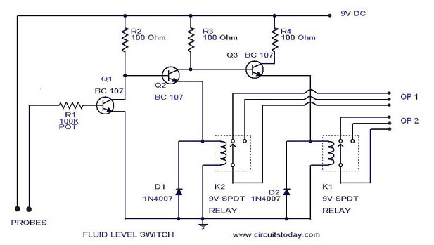
Here is a simple level switch circuit that switches on one relay and switches off another relay when the fluid level exceeds the set limit.This circuit is a modification of the “Simple Water Level Indicator” previously posted.When the water level touches the probes positive supply is connected to the base of Q1 through fluid.This makes transistor Q1 ON.Base of Q2 is connected to collector of Q1 and base of Q3 is connected to collector of Q2.As a result Q1 will be on and Q2 will be OFF.So K2 will be OFF and K1 will be ON.Net result, we get two relays operating according to level ,one ON and Other OFF.The contacts of the relays OP1 and OP2 can be used according to your need to operate any device like motor,pumps,solenoid valves,light,alarm etc.When water level falls K2 will be ON and K1 will be OFF.
Notes
- Adjust R1 keeping probes touched in water to obtain the relay K1 ON.Then remove probes from water and see relay K1 goes OFF.During this time the opposite will be happening in K2.If you cannot attain the setting replace R1 with a 500K POT and repeat the procedure.That’s enough.
- For the probes cut 2 1 sqcm aluminum sheets and connect it to good quality insulated Aluminum wires. 2 cm spacing between probes is enough.Mount the two probes parallely at the desired level.Circuit is ready.
- One problem of this circuit is the corrosion of probes since DC is used.Any way this setup will run problem free for at least one year. We are developing a corrosion free version of the same circuit.That will be here soon.
Read more: http://www.circuitstoday.com/level-switch#ixzz10hq9cnx3
Under Creative Commons License: Attribution