
Photographs © Rapid Electronics
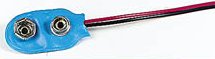
Battery clips and holders
The standard battery clip fits a 9V PP3 battery and many battery holders such as the 6 × AA cell holder shown. Battery holders are also available with wires attached, with pins for PCB mounting, or as a complete box with lid, switch and wires.Many small electronic projects use a 9V PP3 battery but if you wish to use the project for long periods a better choice is a battery holder with 6 AA cells. This has the same voltage but a much longer battery life and it will work out cheaper in the long run.
Larger battery clips fit 9V PP9 batteries but these are rarely used now.


PCB
terminal
block
Terminal block
Photographs © Rapid Electronics
Terminal blocks and PCB terminals
Terminal blocks are usually supplied in 12-way lengths but they can be cut into smaller blocks with a sharp knife, large wire cutters or a junior hacksaw. They are sometimes called 'chocolate blocks' because of the way they can be easily cut to size.PCB mounting terminal blocks provide an easy way of making semi-permanent connections to PCBs. Many are designed to interlock to provide more connections.
Crocodile clips


Crocodile clips
Photographs © Rapid Electronics
The 'standard' crocodile clip has no cover and a screw contact. However, miniature insulated crocodile clips are more suitable for many purposes including test leads. They have a solder contact and lugs which fold down to grip the cable's insulation, increasing the strength of the joint. Remember to feed the cable through the plastic cover before soldering! Add and remove the cover by fully opening the clip, a piece of wood can be used to hold the jaws open.


4mm terminal
and solder tag


Photographs © Rapid Electronics
4mm plugs, sockets and terminals
These are the standard single pole connectors used on meters and other electronic equipment. They are capable of passing high currents (typically 10A) and most designs are very robust. Shrouded plugs and sockets are available for use with high voltages where there is a risk of electric shock. A wide variety of colours is available from most suppliers.Plugs
Plugs may have a screw or solder terminal to hold the cable. Check if you need to thread the cable through the cover before connecting it. Some plugs, such as those illustrated, are 'stackable' which means that they include a socket to accept another plug, allowing several plugs to be connected to the same point - a very useful feature for test leads.
Sockets
These are usually described as 'panel mounting' because they are designed to be fitted to a case. Most sockets have a solder contact but the picture shows other options. Fit the socket in the case before attaching the wire otherwise you will be unable to add the mounting nut.
Terminals
In addition to a socket these have provision for attaching a wire by threading it through a hole (or wrapping it around the post) and tightening the top nut by hand. They usually have a threaded stud to fit a solder tag inside the case.

Photograph © Rapid Electronics
2mm plugs and sockets
These are smaller versions of the 4mm plugs and sockets described above, but terminals are not readily available. The plugs illustrated are stackable. Despite their small size these connectors can pass large currents and some are rated at 10A.DC power plugs and sockets

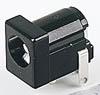
Photographs © Rapid Electronics
These 2-pole plugs and sockets ensure that the polarity of a DC supply cannot be accidentally reversed. The standard sizes are 2.1 and 2.5mm plug diameter. Standard plugs have a 10mm shaft, 'long' plugs have a 14mm shaft. Sockets are available for PCB or chassis mounting and most include a switch on the outer contact which is normally used to disconnect an internal battery when a plug is inserted.
Miniature versions with a 1.3mm diameter plug are used where small size is essential, such as for personal cassette players.


¼" (6.3mm) jack plug and socket


3.5mm jack plug and socket

3.5mm jack line socket
(for fitting to a cable)
Photographs © Rapid Electronics
Jack plugs and sockets
These are intended for audio signals so mono and stereo versions are available. The sizes are determined by the plug diameter: ¼" (6.3mm), 3.5mm and 2.5mm. The 2.5mm size is only available for mono.Screened plugs have metal bodies connected to the COM contact. Most connections are soldered, remember to thread cables through plug covers beforesoldering! Sockets are designed for PCB or chassis mounting.
¼" plug connections are similar to those for 3.5mm plugs shown below. ¼" socket connections are COM, R and L in that order from the mounting nut, ignore R for mono use. Most ¼" sockets have switches on all contacts which open as the plug is inserted so they can be used to isolate internal speakers for example.
The connections for 3.5mm plugs and sockets are shown below. Plugs have a lug which should be folded down to grip the cable's insulation and increase the strength of the joint. 3.5mm mono sockets have a switch contact which can be used to switch off an internal speaker as the plug is inserted. Ignore this contact if you do not require the switching action.

3.5mm jack plug and socket connections
(the R connection is not present on mono plugs)
L = left channel signal
R = right channel signal
COM = common (0V, screen)
Do not use jack plugs for power supply connections because the contacts may be briefly shorted as the plug is inserted. UseDC power connectors for this.


Photographs © Rapid Electronics
Phono plugs and sockets
These are used for screened cables carrying audio and video signals. Stereo connections are made using a pair of phono plugs and sockets. The centre contact is for the signal and the outer contact for the screen (0V, common). Screened plugs have metal bodies connected to the outer contact to give the signal additional protection from electrical noise. Sockets are available for PCB or chassis mounting, singly for mono, or in pairs for stereo. Line sockets are available for making extension leads.
Construction of a screened cable


Photographs © Rapid Electronics
Coax plugs and sockets
These are similar to the phono plugs and sockets described above but they are designed for use with screened cables carrying much higher frequency signals, such as TV aerial leads. They provide better screening because at high frequencies this is essential to reduce electrical noise.
BNC plug, photograph © Rapid Electronics
BNC plugs and sockets
These are designed for screened cables carrying high frequency signals where an undistorted and noise free signal is essential, for example oscilloscope leads. BNC plugs are connected with apush and twist action, to disconnect you need to twist and pull.Plugs and sockets are rated by their impedance (50![]() or 75
or 75![]() ) which must be the same as the cable's impedance. If the connector and cable impedances are not matched the signal will be distorted because it will be partly reflected at the connection, this is the electrical equivalent of the weak reflection which occurs when light passes through a glass window.
) which must be the same as the cable's impedance. If the connector and cable impedances are not matched the signal will be distorted because it will be partly reflected at the connection, this is the electrical equivalent of the weak reflection which occurs when light passes through a glass window.

DIN plug

5 way 180° DIN socket
(chassis mounting)
Photographs © Rapid Electronics
DIN plugs and sockets
These are intended for audio signals but they can be used for other low-current purposes where a multi-way connector is required. They are available from 3 way to 8 way. 5 way is used for stereo audio connections. The contacts are numbered on the connector, but they are not in numerical order! For audio use the 'common' (0V) wire is connected to contact 2. 5 way plugs and sockets are available in two versions: 180° and 270° (the angle refers to the arc formed by the contacts).Plastic covers of DIN plugs (and line sockets) are removed by depressing the retaining lug with a small screwdriver. You may also need small pliers to extract the body from the cover but do not pull on the pins themselves to avoid damage. Remember to thread the cable through the cover before starting to solder the connections!
Soldering DIN plugs is easier if you clamp the insert with the pins. Wires should be pushed into the hollow pins - first 'tin' the wires (coat them with a thin layer of solder) then melt a little solder into the hollow pin and insert the wire while keeping the solder molten. Take care to avoid melting the plastic base, stop and allow the pin to cool if necessary.
Mini-DIN connectors are used for computer equipment such as keyboards and mice but they are not a good choice for general use unless small size is essential.


Photographs © Rapid Electronics
D connectors
These are multi-pole connectors with provision for screw fittings to make semi-permanent connections, for example on computer equipment. The D shape prevents incorrect connection. Standard D-connectors have 2 rows of contacts (top picture); 9, 15 and 25-way versions are the most popular. High Density D-connectors have 3 rows of contacts (bottom picture); a 15-way version is used to connect computer monitors for example.Note that covers (middle picture) are usually sold separately because both plugs and sockets can be fitted to cables by fitting a cover to a chassis mounted connector. PCB mounting versions of plugs and sockets are also available. The contacts are usually numbered on the body of the connector, although you may need a magnifying glass to see the very small markings. Soldering D-connectors requires a steady hand due to the closeness of the contacts, it is easy to accidently unsolder a contact you have just completed while attempting to solder the next one!


Photographs © Rapid Electronics
IDC communication connectors
These multi-pole insulation displacement connectors are used for computer and telecommunications equipment. They automatically cut through the insulation on wires when installed and special tools are required to fit them. They are available as 4, 6 and 8-way versions.The 8-way RJ45 is the standard connector for modern computer networks. If you regularly use these you may be interested in thelead tester project.
Standard UK telephone connectors are similar in style but a slightly different shape. They are called BT (British Telecom) connectors.
Cables
Cable... flex... lead... wire...What do all these terms mean?
- A cable is an assembly of one or more conductors (wires) with some flexibility.
- A flex is the proper name for the flexible cable fitted to mains electrical appliances.
- A lead is a complete assembly of cable and connectors.
- A wire is a single conductor which may have an outer layer of insulation (usually plastic).
Single core equipment wire
Typical specification: 1/0.6mm (1 strand of 0.6mm diameter), maximum current 1.8A.
Stranded wire
Typical specifications:
10/0.1mm (10 strands of 0.1mm diameter), maximum current 0.5A.
7/0.2mm (7 strands of 0.2mm diameter), maximum current 1.4A.
16/0.2mm (16 strands of 0.2mm diameter), maximum current 3A.
24/0.2mm (24 strands of 0.2mm diameter), maximum current 4.5A.
55/0.1mm (55 strands of 0.1mm diameter), maximum current 6A, used for test leads.
'Figure 8' (speaker) cable
![]()
Photograph © Rapid Electronics
'Figure 8' cable consists of two stranded wires arranged in a figure of 8 shape. One wire is usually marked with a line. It is suitable for low voltage, low current (maximum 1A) signals where screening from electrical interference is not required. It is a popular choice for connecting loudspeakers and is often called 'speaker cable'.

Photograph © Rapid Electronics
Signal cable
Signal cable consists of several colour-coded cores of stranded wire housed within an outer plastic sheath. With a typical maximum current of 1A per core it is suitable for low voltage, low current signals where screening from electrical interference is not required.The picture shows 6-core cable, but 4-core and 8-core are also readily available.
![]()
Screened cable (mono)

Screened cable (stereo)

Screened cable (stereo)
Photographs © Rapid Electronics
Screened cable
The diagram shows the construction of screened cable. The central wire carries the signal and the screen is connected to 0V (common) to shield the signal from electrical interference. Screened cable is used for audio signals and dual versions are available for stereo.
Construction of a screened cable
![]()
Photograph © Rapid Electronics
Co-axial cable
This type of screened cable (see above) is designed to carry high frequency signals such as those found in TV aerials and oscilloscope leads.Mains flex

Photograph © Rapid Electronics
Flex is the proper name for the flexible cable used to connect appliances to the mains supply. It contains 2 cores (for live and neutral) or 3 cores (for live, neutral and earth). Mains flex has thick insulation for the high voltage (230V in UK) and it is available with various current ratings: 3A, 6A and 13A are popular sizes in the UK.
Mains flex is sometimes used for low voltage circuits which pass a high current, but please think carefully before using it in this way. The distinctive colours of mains flex should act as a warning of the mains high voltage which can be lethal; using mains flex for low voltage circuits can undermine this warning.
 Circuit symbol:

 Circuit symbol:
 Many small value capacitors have their value printed but without a multiplier, so you need to use experience to work out what the multiplier should be!