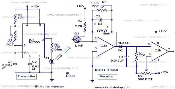
 Here is the circuit diagram of an infrared motion detector that can be used to sense intrusions.Infra red rays reflected from a static object will be in one phase, and the rays reflected from a moving object will be in another phase.The circuit uses this principle to sense the motion.
Custom Search
Friday, September 24, 2010
Infrared motion detector circuit
Here is the circuit diagram of an infrared motion detector that can be used to sense intrusions.Infra red rays reflected from a static object will be in one phase, and the rays reflected from a moving object will be in another phase.The circuit uses this principle to sense the motion.Schmitt Trigger using Op-Amp
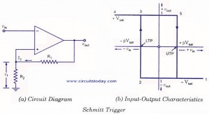
The input voltage vin is applied to the inverting input terminal and the feedback voltage goes to the non-inverting terminal. This means the circuit uses positive voltage feedback instead of negative feedback, that is, in this circuit feedback voltage aids the input voltage rather than opposing it. For instance, assume the inverting input voltage to be slightly positive. This will produce a negative output voltage. The voltage divider feedsback a negative voltage to the non-inverting input, which results in a larger negative voltage. This feedsback more nega tive voltage until the circuit is driven into negative saturation. If the input voltage were, slightly negative instead of positive, the circuit would be driven into the positive saturation. This is the reason the circuit is also referred to as re generative comparator.
Full wave bridge rectifier
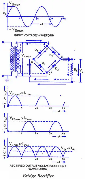
Dur ing this half of each input cycle, the diodes D2 and D4 are reverse biased and so the current is not allowed to flow in arms AD and BC. The flow of current is indicated by solid arrows in the figure. In the second half of the input cycle the lower end of ac supply becomes positive, diodes D,2 and D4 become forward biased and current flows through arm CB, enters the load at the positive terminal, leaves the load at nega tive terminal and returns back flowing through arm DA. Flow of current has been shown by dotted ar rows in the figure. Thus the direction of flow of cur rent through the load resistance RL remains the same during both half^eycles of the input supply voltage.
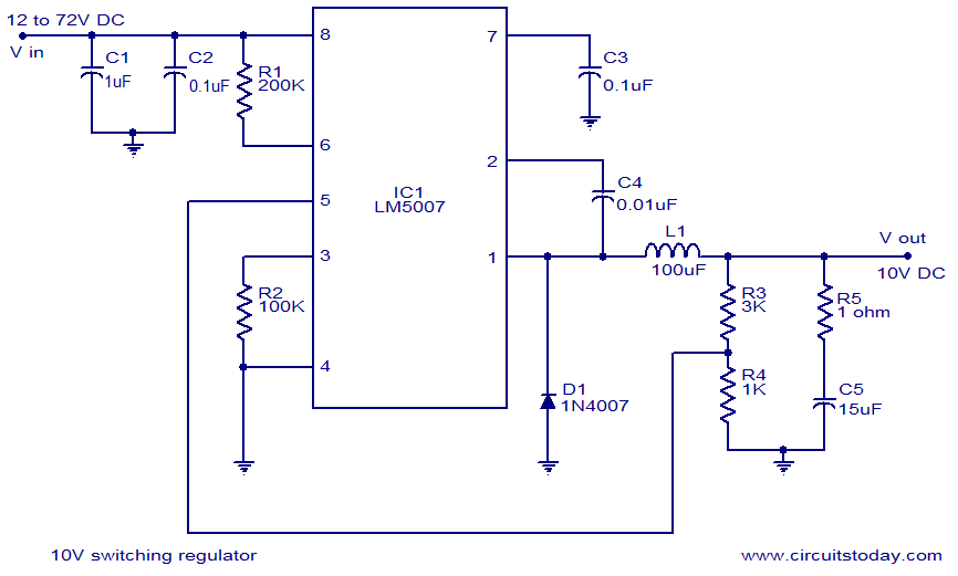
10V switching regulator using LM5007
Analog PID Controller
The circuit diagram below shows us about a form of PID controller. The input signal is buffered and amplified by a non-inverting amplifier and the gain of this stage defines the proportional gain P of the controller.The amplified error signal passes in parallel through an integrator (top) a unity-gain amplifier (middle) and a differentiator (bottom) all of which have inverting behaviour. The final op-amp sum and invert the outputs and passed to the output.
The potentiometers labeled D and I control the proportions in which derivative and integral fractions contribute to the output signal which is proportional to the power W to be supplied to the heater.t is most likely to be troublesome by causing an offset between the set-point and oven temperatures.
Under some circumstances the integrator may drift and eventually saturate which would prevent it from working properly. To reduce the impact of op-amp offset and bias, the first thing to try would be a resistor, equal in value to R2, between the positive input of the integrating op-amp and ground to eliminate the common-mode bias current. Selecting an op-amp with a good input-offset performance would be the next step.
Light detector using a relay

Dark detector using a relay

Subscribe to:
Posts (Atom)