Custom Search

Monday, October 25, 2010

L200 DC Variable power 3-15volt at 2Amp


For the work experiences general that want power supply LAB. I thinks L200 DC Variable power Circuit. May like you , because of give Volt range about 3V-15V and Current 2A normal. When , you see the circuit. May search eyes and the integrated circuit that use be number L200 although old already.


L200 DC Variable power 3-15volt at 2Amp
But still be usable well the interesting. This important circuit that should use Transformer that be appropriate be 12V sizes and should use 2A more than because get current that straight follow want certainly give testimony grandmother horn forget to stick let off the heat gives with, IC L200 with appropriately. The detail is other see in the circuit and from original website
 
http://www.mitedu.freeserve.co.uk/Circuits/Power/l200var.html

2N3055 variable supply 0-25V


One your friend beg for model the circuit about variable supply range 0-25V. I tries to search see meet voltage regulators circuits. The this be the circuit that use the transistor 2N3055 numbers are important equipment. Which be the equipment that seek good easy. fine P1 control current output the topmost.And fine P2 control Voltage range 0-25V.


2N3055 variable supply 0-25V
The detail is other invite read in original website http://www.redcircuits.com//Page36.htm

Variable Regulater Switching LAB Supply 50V 5A by TL494


Somsak is person see the website of me take an interest try build Variable Regulater Switching LAB Supply. By fine decorate voltage output get 0-50V and fine current get 5A. I then choose this circuit , which use IC TL494 be pillar equipment (Switchmode Pulse Width Modulation Control Circuit).


Variable Regulater Switching LAB Supply 50V 5A by TL494
And use pretty litter transistor number MJ15004 then give current get enough tall. But should choose pot size modifies about 5A go up with. When see the circuit has already may inappropriate with a novice. Because use many equipments then the gift uses the tie perhaps specially with , be lucky sir.
 
http://www.circuitpowersupply.com/circuitblog/variable-regulater-switching-lab-supply-50v-5a-by-tl494/

Simple DC voltage regulated 0-30V 3A


If you are looking for DC Voltage Reulator be simple. That can give Current tall about 3A and fine voltage get from 0-30V. As a result please consider this circuit before, it is easy. Because of have no the integrated circuit. Use the transistor is a principle especially the number MJ3001.


Simple DC voltage regulated 0-30V 3A
Usability just fine VR1 for control Volt output and choose the value Current get with S1. The detail is other see in the circuit help understand go up sir.

http://www.circuitpowersupply.com/circuitblog/simple-dc-voltage-regulated-0-30v-3a/

High Current Regulated Supply By LM317 and 2N3055×2


The high current regulator below uses an additional winding or a separate transformer to supply power for the LM317 regulator so that the pass transistors can operate closer to saturation and improve efficiency. For good efficiency the voltage at the collectors of the two parallel 2N3055 pass transistors should be close to the output voltage.
High Current Regulated Supply By LM317 and 2N3055×2
The LM317 requires a couple extra volts on the input side, plus the emitter/base drop of the 3055s, plus whatever is lost across the (0.1 ohm) equalizing resistors (1volt at 10 amps), so a separate transformer and rectifier/filter circuit is used that is a few volts higher than the output voltage. The LM317 will provide over 1 amp of current to drive the bases of the pass transistors and assumming a gain of 10 the combination should deliver 15 amps or more.
By Bill Bowden
Source :: http://ourworld.compuserve.com/homepages/Bill_Bowden/page12.htm

DC Voltage Regulator dual Power Supply +5V to +25V, -5V to -25V 1A with LM7805 LM7905


When you want Dual power supply Variable Regulator be simple. I begs for to advise this circuit, because use the integrated circuit LM7805 and LM7905. Make have Voltage +5V to +25V and -5V to -25V unless. Still pay current get about 1A enough with general usability.


DC Voltage Regulator dual Power Supply +5V to +25V, -5V to -25V 1A with LM7805 LM7905
The important factor is you should use Transformer at enough size doesn’t lower 2A and IC all stick let off the heat with. The detail is other see in circuit picture better sir.

http://www.circuitpowersupply.com/circuitblog/dc-voltage-regulator-dual-power-supply-5v-to-25v-5v-to-25v-1a-with-lm7805-lm7905/

2V to 25V Power Supply Schematic


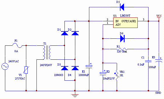
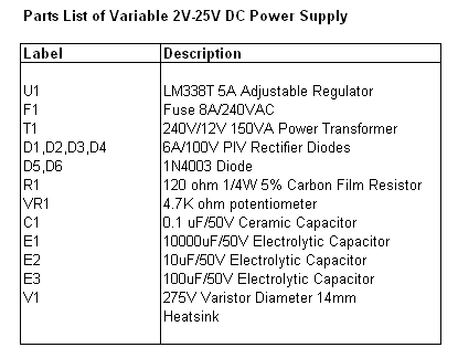
This project uses a LM338 adjustable 3 terminal regulator to supply a current of up to 5A over a variable output voltage of 2V to 25V DC. It will come in handy to power up many electronic circuits when you are assembling or building any electronic devices. The schematic and parts list are designed for a power supply input of 240VAC. Change the ratings of the components if 110VAC power supply input is required.


As shown in the figure above, the mains input is applied to the circuit through fuse F1. The fuse will blow if a current greater than 8A is applied to the system. Varistor V1 is used to clamp down any surge of voltage from the mains to protect the components from breakdown. Transformer T1 is used to step down the incoming voltage to 24V AC where it is rectified by the four diodes D1, D2, D3 and D4. Electrolytic capacitor E1 is used to smoothen the ripple of the rectified DC voltage.

Diodes D5 and D6 are used as a protection devices to prevent capacitors E2 and E3 from discharging through low current points into the regulator. Capacitor C1 is used to bypass high frequency component from the circuit. Ensure that a large heat sinkis mounted to LM338 to transfer the heat generated to the atmosphere.

Parts List


http://www.electronics-project-design.com/PowerSupplySchematic.html

Simple DC Motor Driver


This simple DC motor driver circuit uses a 741 operational amplifier operating as a voltage follower where its non inverting input is connected to the speed and rotation direction of a potentiometer VR1. When VR1 is at mid position, the op-amp output is near zero and both Q1 and Q2 is OFF.

When VR1 is turned towards the positive supply side, the output will go positive voltage and Q1 will supply the current to the motor and Q2 will be OFF. When VR1 is turned to the negative supply side, the op-amp output switches to the negative voltage and Q1 will turn OFF and Q2 ON which reverses the rotation of the motor's direction.

As the potentiometer VR1 is moved toward either end, the speed increases in whichever direction it is turning.

The TIP3055 Q1 NPN power transistor has a collector current specs of 15A and VCE0 of 60V DC.

The MJE34 Q2 PNP power transistor has a collector current specs of 10A and VCE0 of 40V DC.

Parts List


Source : Extracted from Popular Electronics Nov 1997, By Charles D. Rakes

DC Servo Motor Basics


A Servo Motor is a small device that has an output shaft which can be positioned to specific angular positions by sending the servo a Pulse Coded Modulation signal. As the coded signal changes, the angular position of the shaft changes. DC servo motors are used in radio controlled airplanes, radio controlled cars, robots and a host of other applications that one can think of. A picture of a servo motor is as shown below.

Though the servo is small in size, it has a printed circuit board with control circuit built in and a standard servo manufactured by Futaba is model S3003. The power consumed is proportional to the mechanical load, thus saving energy when it is used in a varying type of load. The servo motor consist of a motor, gears and its casing. Three wires are used to interface to other control circuitry which are +5V DC, Ground and Control Signal.

It is using a control called proportional control of which the amount of power applied to the motor is proportional to the distance it needs to travel. This means that if the shaft needs to turn a large distance, the motor will run at higher speed. Usually a servo is used to control an angular motion of between 0 and 180 degrees.

The servo expects to see a pulse every 20 milliseconds (.02 seconds). The length of the pulse will determine how far the motor turns. A 1.5 millisecond pulse, for example, will make the motor turn to the 90 degree position (often called the neutral position). If the pulse is shorter than 1.5 ms, then the motor will turn the shaft to closer to 0 degress. If the pulse is longer than 1.5ms, the shaft turns closer to 180 degress.

DC Servo Motor Driver Circuit Description

The input signals are between 0 - 5V delivered by connecting up the 10K potentiometers as voltage dividers. The Microchip PIC 16C71 has an AD converter that changes the voltage signal into the Pulse Code Modulation system used by the servo motors. This signal is a 5V pulse between 1 and 2 msec long repeated 50 times per second. The width of the pulse determines the position of the server. Most servos will move to the center of their travel when they receive a 1.5msec pulse. One extreme of motion generally equates to a pulse width of 1.0msec; the other extreme to 2.0msec with a smooth variation throughout the range, and neutral at 1.5msec.

It will be a good experience to experiment the control of servo motors in this project by doing your own software programming using PIC 16C71 microcontroller.


http://www.electronics-project-design.com/DCservoMotor.html