Custom Search

Sunday, October 3, 2010

Sync Signal Separator

 This simple sync signal separator circuit separates the composite sync signal into 2 separate horizontal and vertical sync signals.The composite signal can be directly used to drive the monitor’s horizontal sync input. That is why the composite signal line is connected directly to the H-sync line. To get the vertical sync signal, the double monoflop 74LS123 is needed as shown in the circuit diagram. The first monoflop time is somewhat longer than the distance between two line scan pulses. All horizontal line sync pulses are supressed. The second monoflop delivers only vertical sync pulses.

ref:http://electroschematics.com

Electronic Siren Circuit

 The DIY Electronic Siren circuit described here can create three different US-style siren sounds: DIY police, DIY ambulance and fire engine. The desired sound can be selected using switch S1. The circuit can be used in toys (such as model vehicles), as part of an alarm system, and in many other applications. For use in a toy, a BC337 is an adequate device for driver T5, since it is capable of directly driving a 200mW (8Ω) loudspeaker. In this case the current consumption from a 9 V power supply is around 140 mA. If a louder sound is required, a BD136 is recommended: this can drive a 5W (8Ω) loudspeaker.This will be the sound produced with the switch S1 on this positions:
  • a: Fire Brigade Siren
  • b: Police Siren
  • c: Ambulance Siren
The current consumption of the electronic siren from a 12 V supply will then be about 180mA. If still more volume is desired, then T5 (a BD136) can be used as a first driver stage, and a 15W (8Ω) loudspeaker can be connected via output transistor T6. Here an AD162 or an MJ2955 can be used, which, for continuous operation, must be provided with cooling. The peak current consumption of the circuit will now be about 500mA with a 12V power supply. Capacitor C1 is not required for battery operation.

Parts List
R1 = R9 = 2.2KΩ
R2 = 470Ω
R3 = 47KΩ
R4 = R8 = 22KΩ
R5 = R6 = R7 = 18KΩ
R10 = 3.3KΩ
C1 = 100µF/16V
C2 = 2.2µF/16V
C3 = 10µF/16V
C4 = 47µF/16V
C5 = 22nF
C6 = 33nF
C7 = 470µF/16V
T1 = T2 = T3 = T4 = BC547
T5 = see text
T6 = MJ2955, AD162

ref:http://electroschematics.com

12 Volts Transformerless Power Supply

 This 12 Volts transformerless power supply take advantage of the fact that a Zener diode is also a normal diode that conducts current in the forward direction. During one half wave, the current flows via D1 through the load and back via D4, while during the other half wave it flows via D3 and D2. Bear in mind that with this circuit (and with the bridge rectifier version), the zero voltage reference of the DC voltage is not directly connected to the neutral line of the 230-V circuit.This means that it is usually not possible to use this sort of supply to drive a triac, which normally needs such a connection. However, circuits that employ relays can benefit from full-wave rectification. The value of the supply voltage depends on the specifications of the Zener diodes that are used, which can be freely chosen. C2 must be able to handle at least this voltage.
The amount of current that can be delivered depends on the capacitance of C1. With the given value of 220nF, the current is approximately 15mA. A final warning: this sort of circuit is directly connected to mains voltage, which can be lethal. You must never come in contact with this circuit! It is essential to house this circuit safely in a suitable enclosure.

ref:http://electroschematics.com

InfraRed Remote Control Tester

This small InfraRed Remote Control Tester circuit is used for checking the operation of an infrared remote control unit. The circuit is based on the idea of connecting a piezo buzzer directly to an IR receiver IC.Operation of the remote control is indicated by the buzzer making a chattering noise. The circuit is very sensitive and has a range of several metres.
The TSOP1738 integrated IR receiver accepts, amplifies and demodulates the IR signal from the remote control, producing an output with a frequency of around 700 Hz. The piezo buzzer is connected to its output, rendering the signal audible. All the other components are simply concerned with producing a stable 5 V power supply from the 9 V PP3-(6F22) type battery.
Instead of the TSOP1738 similar devices from other manufacturers can be used, and of course carrier frequencies other than 38 kHz can be used. The circuit still works if there is a mismatch between the nominal carrier frequencies of the transmitter and receiver IC, but range is reduced. It is still, however, adequate for determining whether a remote control is producing an IR signal or not.
Ref:http://electroschematics.com

Numeric Water Level Indicator

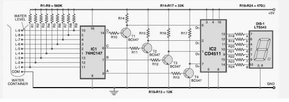
 Most water-level indicators for water tanks are based upon the number of LEDs that glow to indicate the corresponding level of water in the container. Here we present a digital version of the water-level indicator. It uses a 7-segment display to show the water level in numeric form from 0 to 9.The numeric water level indicator circuit works off 5V regulated power supply. It is built around priority encoder IC 74HC147 (IC1), BCD-to-7-segment decoder IC CD4511 (IC2), 7-segment display LTS543 (DIS1) and a few discrete components.
When the water tank is empty, all the inputs of IC1 remain high. As a result, its output also remains high, making all the inputs of IC2 low. Display LTS543 at this stage shows ‘0,’ which means the tank is empty. Similarly, when the water level reaches L-1 position, the display shows ‘1,’ and when the water level reaches L-8 position, the display shows ‘8.’ Finally, when the tank is full, all the inputs of IC1 become low and its output goes low to make all the inputs of IC2 high. Display LTS543 now shows ‘9,’ which means the tank is full.
Assemble the numeric water level circuit on a general-purpose PCB and enclose in a box. Mount 7-segment LTS543 on the front panel of the box. For sensors L-1 though L-9 and ground, use corrosion free conductive-metal (stainless-steel) strips.

Magnetic Field Sensor

 This DIY magnetic field sensor circuit is very simple and can detect fixed magnetic fields or fields that are varying at an audio frequency. The unit is not intended to provide accurate measurement of magnetic field strength.
A small and not very powerfull bar magnet can be detected at about 100 mm from the sensor. It has a Hall Effect sensor (UGN3503U) and IC2 (OP77GP or TL071CP), a precision opamp which is used to provide some additional amplification. Meter ME1 is connected between the output of IC2 and the potential divider and it therefore responds to the voltage difference between the two. If audio rather than DC performance is of most importance it would be advisable to use TL071CP for IC2 and then reduce the output resistor from 33k to 27k.
A 6V battery supplies power to the magnetic field sensor circuit and the current consumption is only about 9mA. Do no use a 9V battery as this will result in the maximum supply voltage rating of IC1 being exceeded.
Testing the magnetic field sensor
When the unit is first switched on it is likely that the meter will be driven fully positive or negative. With careful adjustments of Balance control VR1 it should be possible to zero the meter and placing the probe near any magnetized object should then produce a suitable response.
Applying a “North Pole” close to the surface it will produce a positive reading, and applying a “South Pole” to it generates a negative reading.
Placing the probe against the power cable of any mains powered device that is switched on should produce a 50 Hz “hum” from the earphone.