Custom Search

Thursday, May 15, 2014

Oscilloscopes (CROs)

An oscilloscope is a test instrument which allows you to look at the 'shape' of electrical signals by displaying a graph of voltage against time on its screen. It is like a voltmeter with the valuable extra function of showing how the voltage varies with time. A graticule with a 1cm grid enables you to take measurements of voltage and time from the screen.

The graph, usually called the trace, is drawn by a beam of electrons striking the phosphor coating of the screen making it emit light, usually green or blue. This is similar to the way a television picture is produced.

Oscilloscopes contain a vacuum tube with a cathode(negative electrode) at one end to emit electrons and ananode (positive electrode) to accelerate them so they move rapidly down the tube to the screen. This arrangement is called an electron gun. The tube also contains electrodes to deflect the electron beam up/down and left/right.

The electrons are called cathode rays because they are emitted by the cathode and this gives the oscilloscope its full name of cathode ray oscilloscope or CRO.

A dual trace oscilloscope can display two traces on the screen, allowing you to easily compare the input and output of an amplifier for example. It is well worth paying the modest extra cost to have this facility.

Precautions
  • An oscilloscope should be handled gently to protect its fragile (and expensive) vacuum tube.
  • Oscilloscopes use high voltages to create the electron beam and these remain for some time after switching off - for your own safety do not attempt to examine the inside of an oscilloscope!

Setting up an oscilloscope
Oscilloscopes are complex instruments with many controls and they require some care to set up and use successfully. It is quite easy to 'lose' the trace off the screen if controls are set wrongly!

There is some variation in the arrangement and labelling of the many controls so the following instuctions may need to be adapted for your instrument.

    Oscilloscope trace

    This is what you should see
    after setting up, when there
    is no input signal connected

  1. Switch on the oscilloscope to warm up (it takes a minute or two).
  2. Do not connect the input lead at this stage.
  3. Set the AC/GND/DC switch (by the Y INPUT) to DC.
  4. Set the SWP/X-Y switch to SWP (sweep).
  5. Set Trigger Level to AUTO.
  6. Set Trigger Source to INT (internal, the y input).
  7. Set the Y AMPLIFIER to 5V/cm (a moderate value).
  8. Set the TIMEBASE to 10ms/cm (a moderate speed).
  9. Turn the timebase VARIABLE control to 1 or CAL.
  10. Adjust Y SHIFT (up/down) and X SHIFT (left/right) to give a trace across the middle of the screen, like the picture.
  11. Adjust INTENSITY (brightness) and FOCUS to give a bright, sharp trace.
  12. The oscilloscope is now ready to use!
    Connecting the input lead is described in the next section.
Further information on the controls: Timebase | Y amplifier | AC/GND/DC switch
Connecting an oscilloscope

co-axial lead

Construction of a co-axial lead

Oscilloscope probe

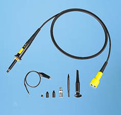
Oscilloscope lead and probes kit
Photograph © Rapid Electronics

The Y INPUT lead to an oscilloscope should be a co-axial lead and the diagram shows its construction. The central wire carries the signal and the screen is connected to earth (0V) to shield the signal from electrical interference (usually called noise).

Most oscilloscopes have a BNC socket for the y input and the lead is connected with a push and twist action, to disconnect you need to twist and pull. Oscilloscopes used in schools may have red and black 4mm sockets so that ordinary, unscreened, 4mm plug leads can be used if necessary.

Professionals use a specially designed lead and probes kit for best results with high frequency signals and when testing high resistance circuits, but this is not essential for simpler work at audio frequencies (up to 20kHz).

An oscilloscope is connected like a voltmeter but you must be aware that the screen (black) connection of the input lead is connected to mains earth at the oscilloscope! This means it must be connected to earth or 0V on the circuit being tested.

Oscilloscope trace of AC

The trace of an AC signal
with the oscilloscope
controls correctly set

Obtaining a clear and stable trace
Once you have connected the oscilloscope to the circuit you wish to test you will need to adjust the controls to obtain a clear and stable trace on the screen:
  • The Y AMPLIFIER (VOLTS/CM) control determines the height of the trace. Choose a setting so the trace occupies at least half the screen height, but does not disappear off the screen.
  • The TIMEBASE (TIME/CM) control determines the rate at which the dot sweeps across the screen. Choose a setting so the trace shows at least one cycle of the signal across the screen.
    Note that a steady DC input signal gives a horizontal line trace for which the timebase setting is not critical.
  • The TRIGGER control is usually best left set to AUTO.

If you are using an oscilloscope for the first time it is best to start with an easy signal such as the output from an AC power pack set to about 4V.


http://electronicsclub.info/cro.htm

Voltage Dividers

A voltage divider consists of two resistances R1 and R2 connected in series across a supply voltage Vs. The supply voltage is divided up between the two resistances to give an output voltage Vo which is the voltage across R2. This depends on the size of R2 relative to R1:

  • If R2 is much smaller than R1, Vo is small (low, almost 0V)
    (because most of the voltage is across R1)
  • If R2 is about the same as R1, Vo is about half Vs
    (because the voltage is shared about equally between R1 and R2)
  • If R2 is much larger than R1, Vo is large (high, almost Vs)
    (because most of the voltage is across R2)
If you need a precise value for the output voltage Vo you can use Ohm's law and a little algebra to work out the formula for Vo shown on the right. The formula and the approximate rules given above assume that negligible current flows from the output. This is true if Vo is connected to a device with a high resistance such as voltmeter or an IC input. For further information please see the page on impedance. If the output is connected to a transistor Vo cannot become much greater than 0.7V because the transistor's base-emitter junction behaves like a diode.

Voltage dividers are also called potential dividers, a name which comes from potential difference (the proper name for voltage).

One of the main uses of voltage dividers is to connect input transducers into circuits...


Using an input transducer (sensor) in a voltage divider

Most input transducers (sensors) vary their resistance and usually a voltage divider is used to convert this to a varyingvoltage which is more useful. The voltage signal can be fed to other parts of the circuit, such as the input to an IC or a transistor switch.

The sensor is one of the resistances in the voltage divider. It can be at the top (R1) or at the bottom (R2), the choice is determined by when you want a large value for the output voltage Vo:

  • Put the sensor at the top (R1) if you want a large Vowhen the sensor has a small resistance.
  • Put the sensor at the bottom (R2) if you want a large Vo when the sensor has a large resistance.
Then you need to choose a value for the resistor...
Choosing a resistor value

voltage divider with LDR at top

OR

voltage divider with LDR at bottom

The value of the resistor R will determine the range of the output voltage Vo. For best results you need a large 'swing' (range) for Vo and this is achieved if the resistor is much larger than the sensor's minimum resistance Rmin, but much smaller than the sensor's maximum resistance Rmax.

You can use a multimeter to help you find the minimum and maximum values of the sensor's resistance (Rmin and Rmax). There is no need to be precise, approximate values will do.

Then choose resistor value:  R = square root of (Rmin × Rmax)
Choose a standard value which is close to this calculated value.

For example:
An LDR: Rmin = 100ohm, Rmax = 1Mohm, so R = square root of (100 × 1M) = 10kohm.

swapping over the resistor and sensor
The resistor and sensor can be swapped over to invert the action of the voltage divider. For example an LDR has a high resistance when dark and a low resistance when brightly lit, so:
  • If the LDR is at the top (near +Vs),
    Vo will be low in the dark and high in bright light.
  • If the LDR is at the bottom (near 0V),
    Vo will be high in the dark and low in bright light.

Using a variable resistor

voltage divider with variable resistor and LDR

The sensor and variable
resistor can be swapped
over if necessary

A variable resistor may be used in place of the fixed resistor R. It will enable you to adjust the output voltage Vo for a given resistance of the sensor. For example you can use a variable resistor to set the exact brightness level which makes an IC change state.

The variable resistor value should be larger than the fixed resistor value. For finer control you can use a fixed resistor in series with the variable resistor. For example if a 10kohm fixed resistor is suitable you could replace it with a fixed 4.7kohm resistor in series with a 10kohm variable resistor, allowing you to adjust the resistance from 4.7k to 14.7kohm.

If you are planning to use a variable resistor connected between the +Vs supply and the base of a transistor you must include a resistor in series with the variable resistor. This is to prevent excessive base current destroying the transistor when the variable resistor is reduced to zero. For further information please see the page on Transistor Circuits.


http://electronicsclub.info/vdivider.htm

Voltage and Current

Voltage attempts to make a current flow, and current will flow if the circuit is complete. Voltage is sometimes described as the 'push' or 'force' of the electricity, it isn't really a force but this may help you to imagine what is happening. It is possible to have voltage without current, but current cannot flow without voltage.

Switch closed
Switch open
No cell

Voltage and Current
The switch is closed making a complete circuit so current can flow.
Voltage but No Current
The switch is open so the circuit is broken and current cannot flow.
No Voltage and No Current
Without the cell there is no source of voltage so current cannot flow.


Voltage, V

Connecting a voltmeter in parallel

Connecting a voltmeter in parallel

  • Voltage is a measure of the energy carried by the charge.
    Strictly: voltage is the "energy per unit charge".
  • The proper name for voltage is potential difference or p.d. for short, but this term is rarely used in electronics.
  • Voltage is supplied by the battery (or power supply).
  • Voltage is used up in components, but not in wires.
  • We say voltage across a component.
  • Voltage is measured in volts, V.
  • Voltage is measured with a voltmeter, connected in parallel.
  • The symbol V is used for voltage in equations.
Voltage at a point and 0V (zero volts)
Voltages at pointsVoltage is a difference between two points, but in electronics we often refer to voltage at a point meaning the voltage difference between that point and a reference point of 0V (zero volts).

Zero volts could be any point in the circuit, but to be consistent it is normally the negative terminal of the battery or power supply. You will often see circuit diagrams labelled with 0V as a reminder.

You may find it helpful to think of voltage like height in geography. The reference point of zero height is the mean (average) sea level and all heights are measured from that point. The zero volts in an electronic circuit is like the mean sea level in geography.

Dual Supply

Zero volts for circuits with a dual supply
Some circuits require a dual supply with three supply connections as shown in the diagram. For these circuits the zero volts reference point is the middle terminal between the two parts of the supply.

On complex circuit diagrams using a dual supply the earth symbol is often used to indicate a connection to 0V, this helps to reduce the number of wires drawn on the diagram.

The diagram shows a ±9V dual supply, the positive terminal is +9V, the negative terminal is -9V and the middle terminal is 0V.


Connecting an ammeter in series

Connecting an ammeter in series

Current, I
  • Current is the rate of flow of charge.
  • Current is not used up, what flows into a component must flow out.
  • We say current through a component.
  • Current is measured in amps (amperes), A.
  • Current is measured with an ammeter, connected in series.
    To connect in series you must break the circuit and put the ammeter acoss the gap, as shown in the diagram.
  • The symbol I is used for current in equations.
    Why is the letter I used for current? ... please see FAQ.
1A (1 amp) is quite a large current for electronics, so mA (milliamps) are often used. m (milli) means "thousandth":

1mA = 0.001A, or 1000mA = 1A

The need to break the circuit to connect in series means that ammeters are difficult to use on soldered circuits. Most testing in electronics is done with voltmeters which can be easily connected without disturbing circuits.


Voltage and Current in Series
Voltage and Current for components in Series
Voltages add up for components connected in series.
Currents are the same through all components connected in series.

In this circuit the 4V across the resistor and the 2V across the LED add up to the battery voltage: 2V + 4V = 6V.

The current through all parts (battery, resistor and LED) is 20mA.


Voltage and Current in Parallel
Voltage and Current for components in Parallel
Voltages are the same across all components connected in parallel.
Currents add up for components connected in parallel.

In this circuit the battery, resistor and lamp all have 6V across them.

The 30mA current through the resistor and the 60mA current through the lamp add up to the 90mA current through the battery.


http://electronicsclub.info/voltage.htm

Analogue and Digital Systems

Analogue signal

Analogue signal

Analogue display

Analogue meter display

Analogue systems
Analogue systems process analogue signals which can take any value within a range, for example the output from an LDR (light sensor) or a microphone.

An audio amplifier is an example of an analogue system. The amplifier produces an output voltage which can be any value within the range of its power supply.

An analogue meter can display any value within the range available on its scale. However, the precision of readings is limited by our ability to read them. For example the meter on the right shows 1.25V because the pointer is estimated to be half way between 1.2 and 1.3. The analogue meter can show any value between 1.2 and 1.3 but we are unable to read the scale more precisely than about half a division.

All electronic circuits suffer from 'noise' which is unwanted signal mixed in with the desired signal, for example an audio amplifier may pick up some mains 'hum' (the 50Hz frequency of the UK mains electricity supply). Noise can be difficult to eliminate from analogue signals because it may be hard to distinguish from the desired signal.


Digital signal

Digital (logic) signal

Digital display

Digital meter display

Digital systems
Digital systems process digital signals which can take only a limited number of values (discrete steps), usually just two values are used: the positive supply voltage (+Vs) and zero volts (0V).

Digital systems contain devices such as logic gates, flip-flops, shift registers and counters. A computer is an example of a digital system.

A digital meter can display many values, but not every value within its range. For example the display on the right can show 6.25 and 6.26 but not a value between them. This is not a problem because digital meters normally have sufficient digits to show values more precisely than it is possible to read an analogue display.

Logic signals

Logic states

True
False

1
0

High
Low

+Vs
0V

On
Off

Most digital systems use the simplest possible type of signal which has just two values. This type of signal is called a logic signal because the two values (or states) can be called true and false. Normally the positive supply voltage +Vs represents true and 0V represents false. Other labels for the true and false states are shown in the table on the right.

Noise is relatively easy to eliminate from digital signals because it is easy to distinguish from the desired signal which can only have particular values. For example: if the signal is meant to be +5V (true) or 0V (false), noise of up to 2.5V can be eliminated by treating all voltages greater than 2.5V as true and all voltages less than 2.5V as false.


http://electronicsclub.info/analogue.htm