Custom Search

Sunday, October 24, 2010

Controlling the speed of 3 phase induction motors

The speed of a normal 3-phase induction motor is a function of the frequency of the supply voltage. Changing the speed of such a motor hence requires building a 3-phase power frequency convertor. The driver can be realised using power mosfets (or IGTB's) capable of handling high voltages and fast switching speeds. The generated frequency can be programmed in a small PIC controller and even in a fast Basic Stamp.

Note that at lower than normal frequencies, the voltage should be decreased proportionally. If you forget this, the motor may overheat and eventually even burn out. (See note at the bottom of this paragraph). The circuits shown here serve mere educational purposes (although they do work!) and are not always the most suitable nor safest sollution.

For the bipolar drive circuit shown below, the motor should be delta-connected.
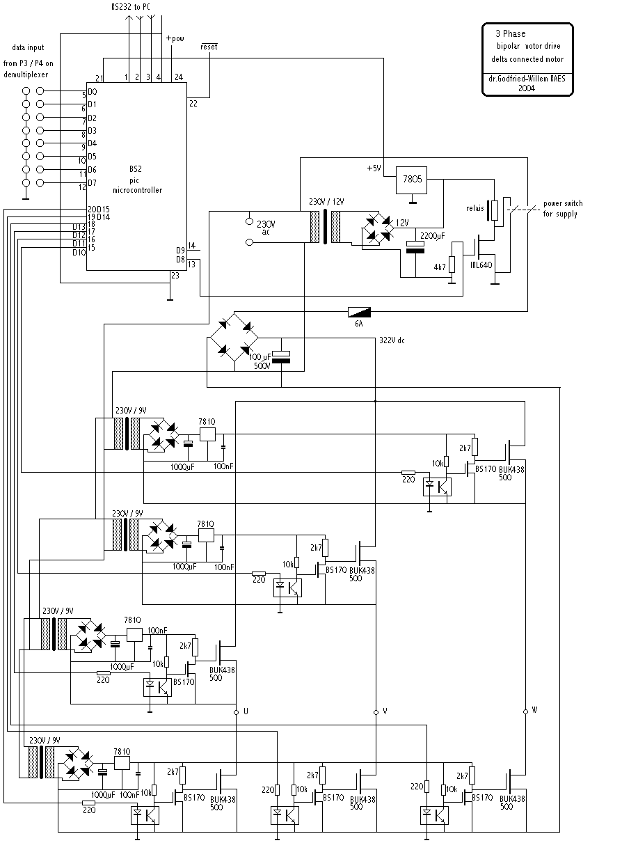
The optocouplers used can be either TIL111 or CNY17-2. Do not try to save on the transformers: these are very small and cheap types (2VA is enough) and the floating way they are connected here (no grounded negative poles!) is essential to this design. Be carefull when playing around with this kind of circuitry, since there are high voltages everywhere. The digital input and the microcontroller are completely and optically isolated from the power circuitry.

The bit-pattern to be programmed in the controller software could look like:
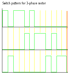
Note the 120 degree phase shift. The pattern was designed to generate a lot of thirth harmonic distortion on the resulting wave, thus increasing the RMS voltage over the motor windings.

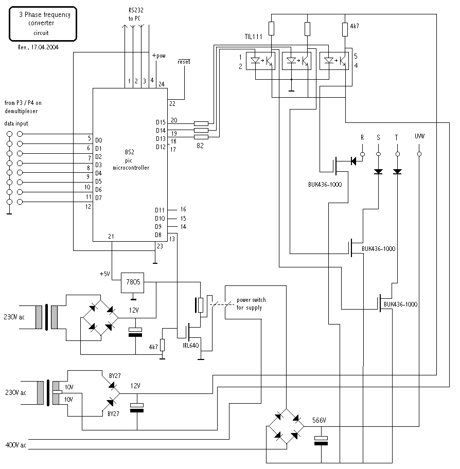
If you want the motor to be Y-connected, the problem will be that you need a much higher voltage to work from. Using a 3-phase rectifier bridge, you can of course use rectified 3-phase mains current, but that presupposes its availability. Ass an alternative an insulation transformer 230V/ 400V can be used. However, at the end this will tend to be more expensive than the circuit given above. The circuit below however will become a lot simpler, since we do not require 6 mosfets and no floating powers supplies:
Applications:

  • changing/ adjusting the wind pressure in windblown organs.
  • Motor controllers for lathes, large saws etc...
  • 3-phase current generator
  • Brushless DC motor drives

NOTE:

If you are in need of a controller for a 3-phase motor, you should always consider using one of the many modules the industry offers these days. Factories such as Lust gmbh, Siemens (Micromaster 410), Toshiba, Hitachi... all have controll modules in their catalogues. Controlling the speed of the motor using such a standard solution can be done by sending an analog voltage (0-10V most of the time) to the appropriate input, or, on some models, by sending RS232 commands to their port. The advantage of these modules is, amongst other things, that they serve as a motor protector at the same time. Also, it might at the end be cheaper than building the circuits shown above yourself.


http://www.logosfoundation.org/kursus/2113.html

6-transistor H-bridge


This is the six transistor "Tilden style" H-bridge; while not as old as the original "basic H-bridge," this goes "way back," and is the basis for many BEAM driver circuits

  • Up to 800 mA capacity (using PN2222 and PN2907 transistors)
  • 30 connections per bridge (so, 30 holes if you make a PCB)
  • Not "smoke-proof" (i.e., it can't handle drive voltage in both directions at once)


You can read the original Tilden article (complete with ASCII art) here.

This circuit comes in two flavors -- one triggers on positive input (non-inverting), the other triggers on negative input (inverting).

Freeforming Courtesy of Bruce Robinson, here are diagrams for free-forming both the inverting and non-inverting flavors of this circuit (note that these are drawn "dead bug" style, i.e., with leads "up"):

ImageImage

Bruce Robinson explains:

I did a couple of revised drawings for Ian quite a while back, so he could put them up at beam-online. Unfortunately, they didn't get posted in the midst of the many revisions he was making.

Attached (begging Ian's indulgence), are the two versions of the circuit, one which turns on with a Positive input, the other (for quadcores) with a Negative input.

Ian shows 100k input resistors. I've been using 47k resistors successfully. Tilden's article recommends nothing lower than 50k (I assumed 47k was close enough) and up to 20 Meg or so.

I've also noticed a slight drop in speed when I use these bridges, but only about 10% or so.

http://library.solarbotics.net/circuits/driver_tilden.html

4-transistor H-bridge

Steve Bolt came up with an interesting 4-transistor H-bridge variant; this is cheap and easy to build, and best of all is "smokeless" (i.e., no combination of inputs can cause the bridge to self-destruct). Here's Steve's diagram:

Image

You should bear the following things in mind with this design:

  • 2N2905 and 2N2219 transistors are no longer being produced; I use 2N2907 and 2N2222 transistors in this circuit, with good results.
  • You absolutely must use one bias resistor per transistor; I attempted to simplify the circuit by connecting the respective transistors' bases (so each pair of transistors could "share" a resistor) -- this made for a circuit that was simpler, much easier to freeform, and completely non-functional.
  • This efficiency of this design is driven by 2 things -- the efficiency of the motor it's driving, and the size of the bias resistors. Just to make life interesting, these things are interrelated (more on this later).
  • This bridge is "smokeable" -- but only if power is supplied to the bridge while the control inputs are allowed to "float" (easy thing to avoid in yourcircuit design).
  • When I first started tinkering with this circuit, I made the assumption that the inverters pictured in Steve's diagram were not intrinsic parts of the bridge, but instead were examples of the outputs coming from the "driving" circuit. This is very, very wrong. If you don't include inverters (or, at least buffers) on the control inputs, you now have to take great care to avoid having the bridge influence the circuit that's driving it.

Since your circuit may or may not (and most likely, won't) have spare buffers / inverters available for use on the H-bridge control inputs, I've done some experimenting on the bridge circuit sans inverters -- let's call this variant "Bolt light."

Freeforming

If you want to build a "freeform" version of the "Bolt light" circuit, here's a very compact layout (note that this diagram shows the transistors in "dead-bug" fashion, i.e., with the chips "down," and their legs pointing up towards you).

I've found it's easiest to solder the outside (motor lead) connections first, then the inside (Vcc / ground) connections, then the middle (resistor) connections. Note that two resistor leads "bridge over" the top of the transistor packages (these hidden leads are shown as dashed lines).


http://library.solarbotics.net/circuits/driver_4varHbridge.html