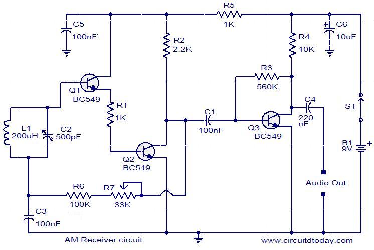
Here is a low cost AM receiver circuit that can be tuned from around 550 to 1100 KHz. Three transistors are used in this project. The transistors Q1 and Q2 are wired as a compound transistor pair in which Q1 is an emitter follower and Q2 is a common emitter amplifier. The emitter follower prevents the loading of tank circuit, while the common emitter amplifier necessary voltage gain. The L1 and C2 forms the tank circuit.The L1 also does the job of antenna.The series combination of R6 and R7 gives a regenerative feedback between output of the Q2 and tank circuit. The transistor Q3 performs the demodulation of the carrier signal. It also provides amplification the demodulated signal. The audio output is coupled out from the collector of Q3 via the capacitor C3.Capacitor C6 provides some noise filtering.