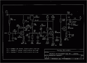
A simple fm radio transmitter circuit which covers frequencies from 88 to 108 MHz. It is built with 3 transistors: BC109, BFR91A and BFR96S. It is quite stable and the output power is around 200 mW.
The first stage in a mic amplifier but if you connect this radio transmitter directly to an audio source you can remove this stage and connect the audio signal to R5.U1, 1PH51C can be replaced with LM7805. You must use a stabilized power source for oscillator stage to prevent frequency variation. You can remove C7 and use a linear potentiometer insted of R6 with the median connector to C4, one pin to ground and the other one to +. You may replace BB109 varicap diode with BB139.
All coils must be perpendicular one to the other, especially L2 and L3. The oscillator stage must be encased with a copper 1mm foil. If you use an external antenna, like this fm dipole antenna connect it with a good coaxial cable because the power is low and you want to use most of it. If you don’t want to loose the rf power connect the radio transmitter close to the antenna (2 meter coaxial cable) and use a longer cable for the audio signal (coaxial). If you connect the antenna as I told you before you can cover a 300 meter in diameter area.
http://electroschematics.com/2498/radio-transmitter-circuit/

